Hydrothermal Reaction Apparatus (HydRA)
Flow-through facility to investigate fluid-rock interactions for geothermal energy utilization
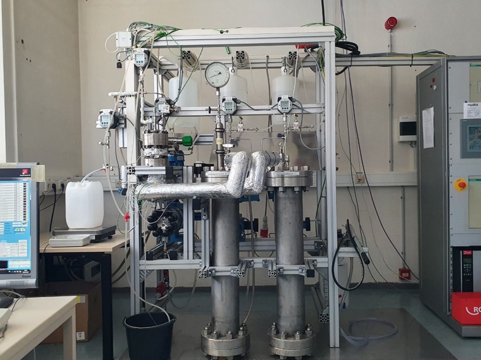
Fig. 1: Photo of the HydRA facility
Motivation
To use geothermal energy the heat is extracted from the brine in a heat exchanger on the surface. The cooled water is reinjected into the reservoir rock by a re-injection well.
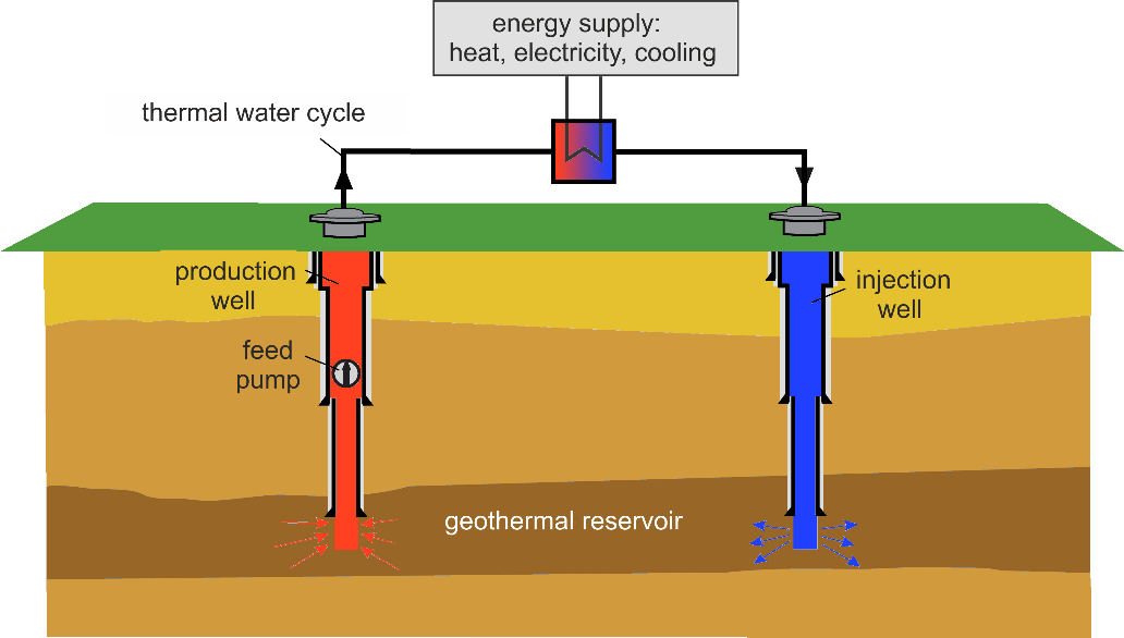
Layout of a geothermal power plant (Fig taken from: umweltbundesamt.de, English translation)
By cooling or lowering the pressure of the usually high saline water within the power plant, the solubility of many of the dissolved salts decreases, which can precipitate them. The precipitation of supersaturated salts can lead to clogging of the pipes and to blockage of the rock pores or joints. This requires at constant flow rate higher and higher pressures for re-injection of the cooled thermal water. Even a failure of the geothermal power plant, and thus an economic loss, is not excluded.
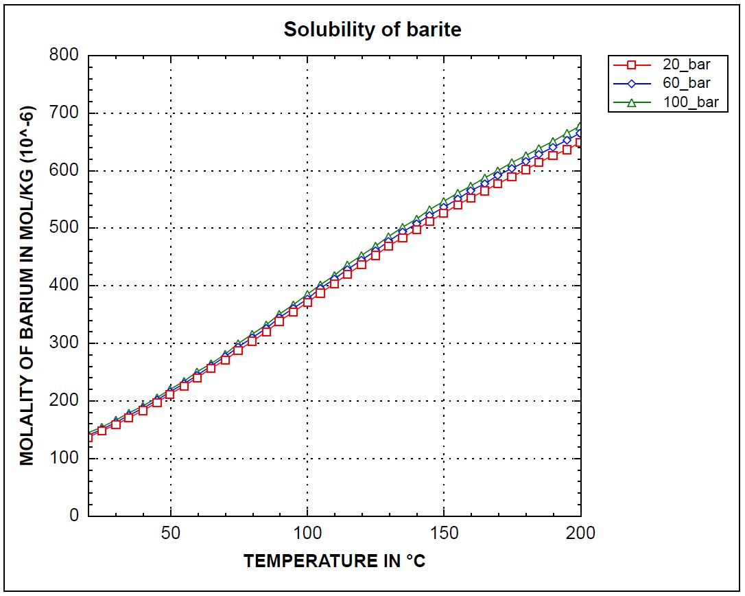
Fig. 3: The example shows the solubility of barium sulfate (barite) in the Upper Rhine Graben: Lowering of temperature leads to a reduced solubility => barite precipitates [Modeling with PHREEQC (Parkhurst and Appelo, 1999 and 2013), Pitzer database]
HydRA (Hydrothermal Reaction Apparatus)
The HydRA facility can be used to perform experiments investigating fluid-rock interactions of geothermal water. The system simulates realistic pressure and temperature conditions to be found in the aquifer of a geothermal well several kilometers in depth, and maps the processes taking place between the thermal water and the surrounding rock. Thus, the phenomena of re-injection of thermal water into the reservoir rock can be investigated at the HydRA facility. The investigations are aimed at the relevant chemical processes, such as precipitation / scaling in the reservoir rock, as well as the chemical-hydraulic coupling during a flow through porous media.
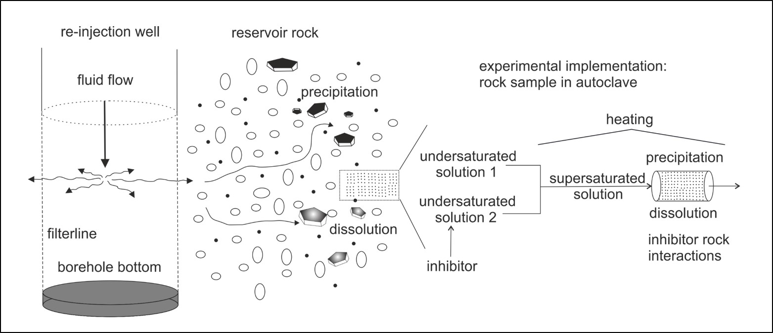
Fig. 4: Transfer of the real occurring phenomena in the reservoir rock to the HydRA technical installation
In the HydRA facility real or artificial geothermal waters can be flowed through a real or artificial rock sample in the presence of pressure and temperature similar to these reservoirs. In this way, precipitation processes can be investigated and possible countermeasures, such as the use of precipitation inhibitors, can be examined.
Main components of the HydRA-facility
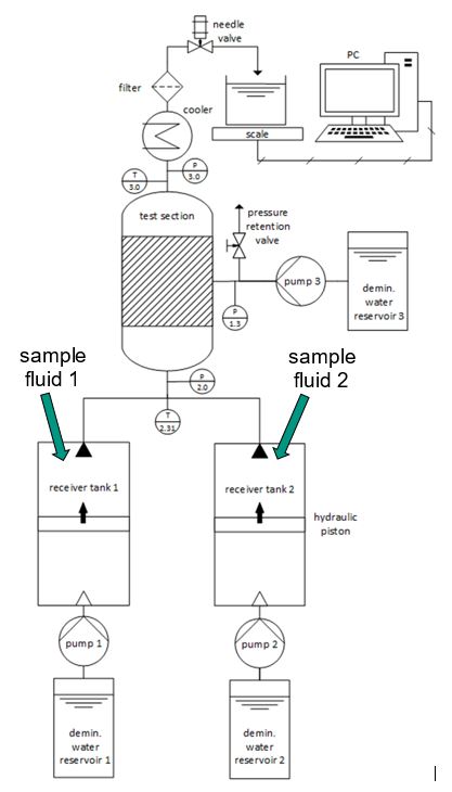
Fig. 5: Main components of the HydRA facility
The HydRA facility possesses two receiver tanks that can be filled with artificial or real thermal water. Each cylindrical receiver tank contains a piston which separates its volume into an upper and a lower part, with the saline thermal water being stored in the upper part. The two pumps 1 and 2 convey demineralized water into the lower parts of the tanks, thus pushing the pistons upwards. In this way the potential corrosive thermal water is transported to the experimental plant via two supply lines without any contact to the internal parts of the pumps. In the mixing section, the two solutions are mixed in equal portions by a mixing tee and then enter the reaction zone (= test section), where the mixture flows through the rock specimen. Only by mixing both solutions, supersaturation of the mineral phase occurs. After the test section, there is a cooler, a filter and a needle valve, which keeps a constant pressure after the rock sample. The system is equipped with pressure probes and thermocouples, whose signals are recorded and stored. The outflowing water is collected in a container which is placed on a scale. It also transmits the signals to the data acquisition system to determine mass flows. Both supply lines as well as the mixing and reaction zones can be heated separately.
Technical data
- Pressure: up to 420 bar
- Temperature: up to 250 °C
- Mass flow: up to 10 g/min
- Possibility of adding of the sample fluids by two separate mass flows (e. g. two undersaturated solutions, which are supersaturated after mixing)
- Automated continuous operation is possible: PLC-monitored control and shutdown when a predefined system status is reached
- Automated data acquisition of pressures, temperatures and total mass flow
Rock samples
The cylindric rock sample (diameter: 1 inch, length: two inches) inside the test section is contained in a tight-fitting silicone tube (see fig. 6), which allows the cones of the pressure flanges above and below it to be pressed tightly against the top and bottom of the rock sample.
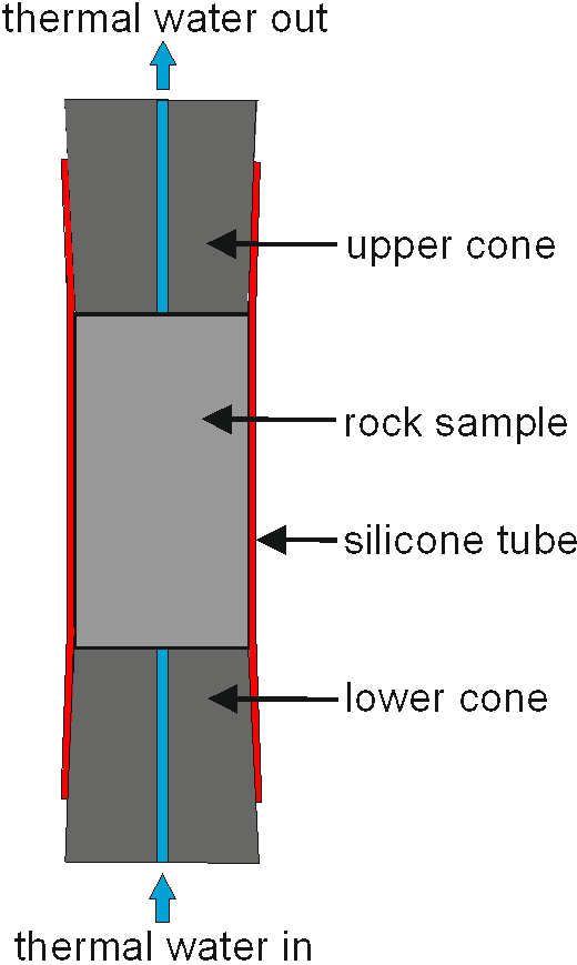
Fig. 6: Installation situation for a compact drill core
Pressure conditions
The fluid flows through the rock sample in a bottom-up direction. To ensure that the fluid flows through the rock and does not bypass it, from the outside, a jacket pressure (p1.3) is applied to the silicone hose, which presses the hose against the outside of the sample cylinder (see fig. 7). To achieve this, in the experiments pressure p1.3 must always be higher than the pressures p2.0 and p3.0.
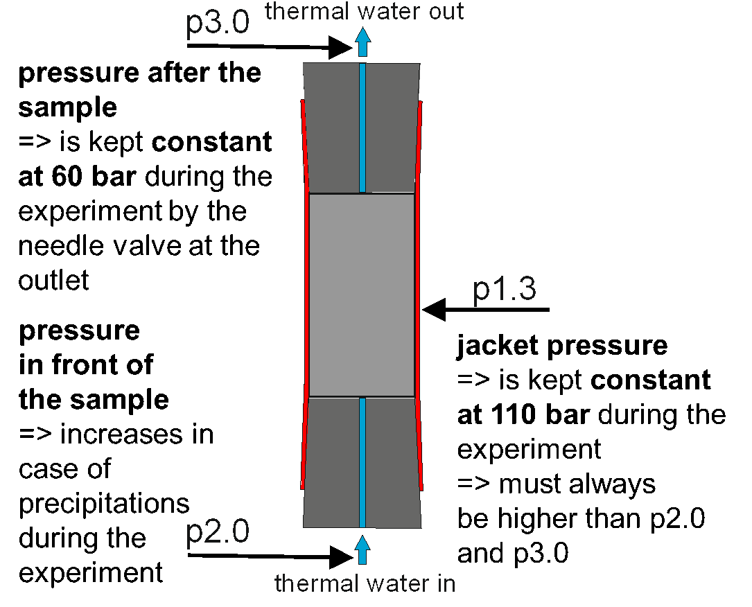
Fig. 7: Pressure conditions in the HydRA experiments
While the experiment is running, the needle valve at the outlet of the system is set to a constant pressure p3.0. The jacket pressure p1.3 is 50 bar higher. At the beginning of an experiment, pressure p2.0 is approximately the same as pressure p3.0. Precipitation of solids in the rock sample can be detected by a continuous increase of pressure in front of the sample (p2.0). However, the pressure after the rock (p3.0) is still maintained at the pressure that was pre-set.
Installation situations of the rock samples
a) Compact rock (example: red sandstone from Lahr, Black Forest, Germany):
The rock samples used in the HydRA facility are drill cores with a diameter of 1 inch and a length of 2 inches. Red sandstone from Lahr can be used as a compact rock sample (see Fig. 6), as its porosity is high enough to allow a through-flow.
b) Protected rock (example: Meletta sandstone near Nußloch, south of Heidelberg, Germany):
Since the rock is only slightly consolidated, a correspondingly shortened rock cylinder is enclosed between borosilicate sintered glass discs to prevent rock particles from being washed out, which can lead to leakage in the needle valve at the outlet.
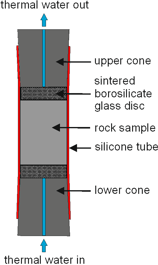
Fig. 8: Installation situation for a protected drill core
c) Rock particles (example: dolomite from Wachenzell, Upper Bavaria, Germany): Since a compact rock cylinder is not permeable, a particle bed of dolomite (Ø 0,71 mm ... 1,00 mm) is used.
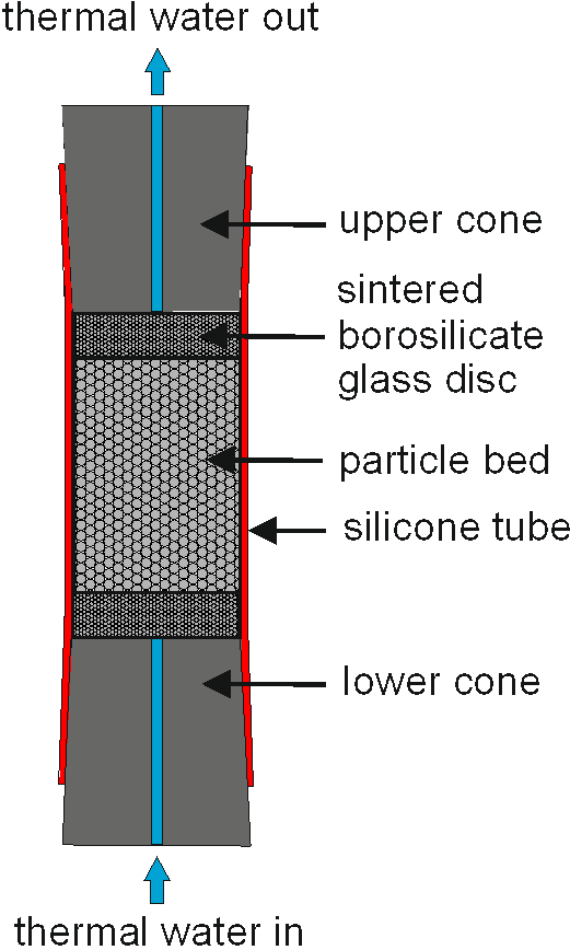
Fig. 9: Installation situation for rock particles in a particle bed
d) Rock flour in a cladding tube (example: contorta sandstone from Schwerin, Mecklenburg–Western Pomerania, Germany) The production of drill cores is not practicable because the rock is only slightly consolidated. Therefore, pressed rock flour in a cladding tube is used.
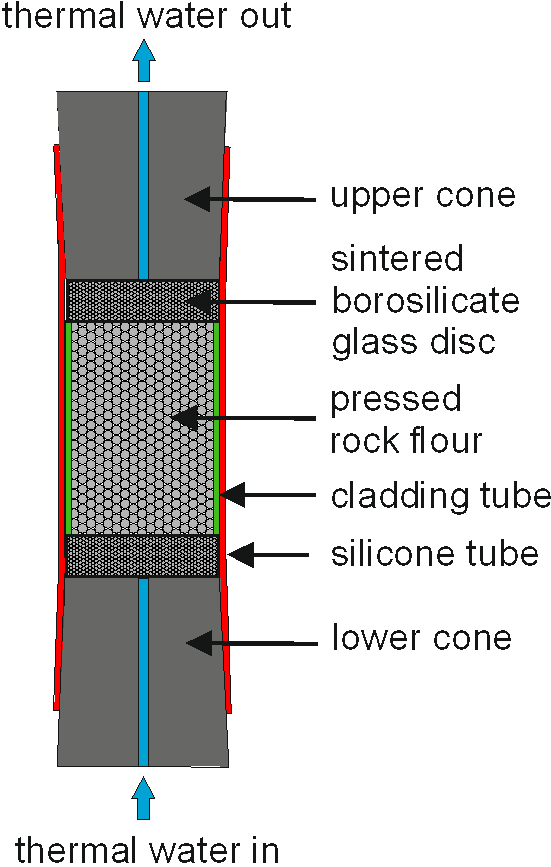
Fig. 10: Installation situation for slightly consolidated rock samples
Pressure curves without and with precipitation inhibitor
Precipitation (e. g. of barite = BaSO4) in the rock pores leads to a pressure rise in front of the sample.
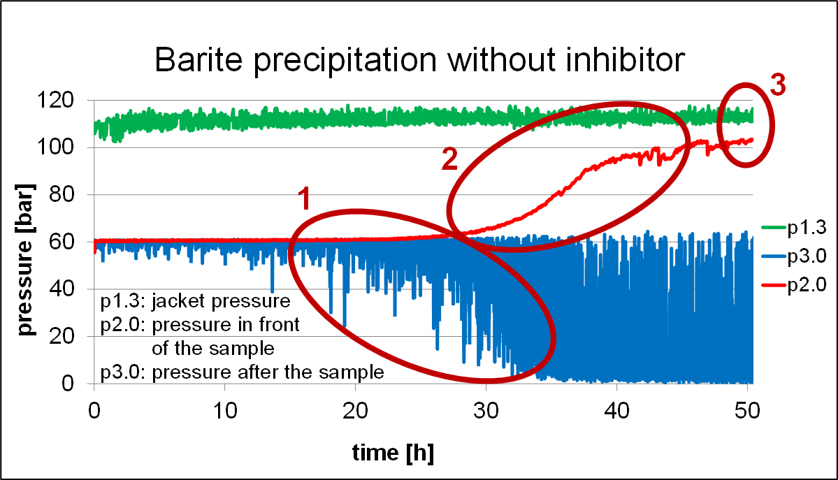
Fig. 11: Without inhibitor a pressure increase across the rock sample arises (red curve)
In case of rock blocking, the following characteristic pressure curve occurs in the HydRA facility:
- Decreasing permeability => increasing pressure fluctuations of p3.0
- Pressure rise across the rock => Δp = p2.0 - p3.0 => increasing
- Reaching the shutdown criterion: the PLC switches off automatically in case p2.0 = 0.95 • p1.3
When using an inhibitor, there is no increase in pressure in front of the rock sample. The permeability of the rock is maintained.
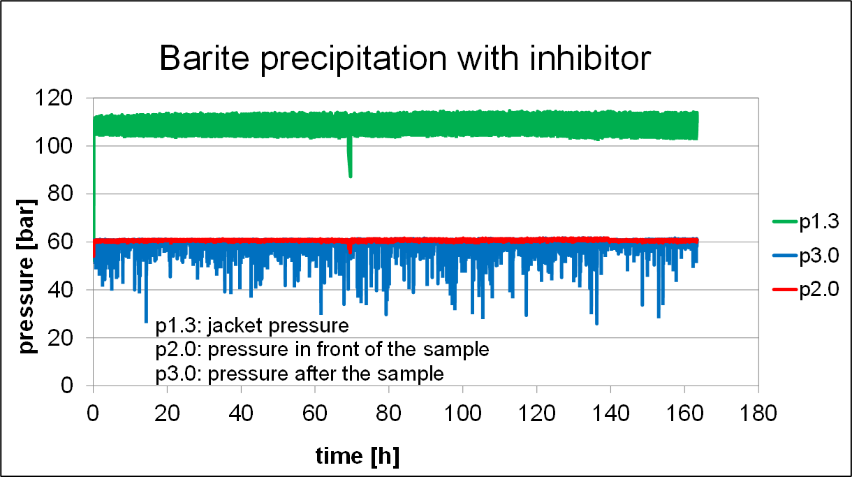
Fig. 12: With inhibitor no pressure increase across the rock sample arises (red curve)
Measurement parameters
- Measurement of the pressure rise across the rock sample as a measure of the clogging of the pores and joints in the reservoir rocks
- Online measurement of fluid parameters of the brine after passing the HydRA facility:
- pH value
- electrical conductivity - Offline measurement chemical analysis by discontinuous sampling of the solution after passing the facility: Determination of cations by inductively coupled plasma optical emission spectrometry (ICP-OES)
- Examination of the rock samples after the experiment using surface analysis methods such as SEM, EDX etc.
Applications
- Studies on the efficiency of precipitation inhibitors in geothermal water during geothermal use
- inhibitor selection
- inhibitor concentration - Studies on inhibitor-rock interactions
- precipitation
- dissolution - Validation experiments for geochemical modeling
- Conditioning of rock samples for further investigations (e.g. SEM, EDX etc.)
Literature
BAUR, S., SEIBT, A., BUSE, C., WOLTER, F. & KUHN, D.: Procedure for the Determination of Rock-Fluid Interaction Reactions with Barium Sulfate Supersaturated Fluids, Proceedings, 49th Workshop on Geothermal Reservoir Engineering, 2024 (2024)
BAUR, S., SEIBT, A., & KUHN, D.: Laboratory flow-through experiments to determine the effect of inhibitors in the injection of fluids supersaturated with barium sulfate, Proceedings, European Geothermal Congress 2022 (2022)
BAUR, S., SEIBT, A., BUSE, C., STERN, G. & KUHN, D.: Experiments at the HydRA rock flow-through facility on the influence of an inhibitor to prevent calcite precipitation in the molasse basin, Proceedings, Geothermal Congress DGK 2021 (2021)
BAUR, S., NEUBERGER, A.-K., KUHN, D. & SEIBT, A.: Measurements on Fluid-Rock-Interaction of Thermal Water-Inhibitor-Mixtures with the HydRA Facility, Proceedings, World Geothermal Congress 2020+1 (2021).
ORYWALL, P., DRÜPPEL, K., KUHN, D., KOHL, T., ZIMMERMANN, M. & EICHE, E.: Flow-through experiments on the interaction of sandstone with Ba-rich fluids at geothermal conditions, Geothermal Energy (2017) 5:20, DOI 10.1186/s40517-017-0079-7
ORYWALL, P., KUHN, D., MUNDHENK, N., MAYER, D. & KOHL, T.: Percolation of porous media under deep geothermal conditions - Investigation of hydraulic effects as a consequence of induced barite scaling, Proceedings, Geothermal Congress DGK 2015 (2015)
PARKHURST, D. L. & APPELO, C. A. J.: User's Guide to PHREEQC (Version 2) - A Computer Program for Speciation, Batch Reaction, one Dimensional Transport, and Inverse Geochemical Calculations. Water-Resources Investigations Report 99-4259. U.S. Geological Survey, Denver, Colorado (1999).
PARKHURST, D. L. & APPELO, C. A. J.: Description of Input and Examples for PHREEQC Version 3 - A Computer Program for Speciation, Batch-Reaction, One-Dimensional Transport, and Inverse Geochemical Calculations. U.S. Geological Survey Techniques and Methods (2013).